
One of the most overloaded terms in the computer industry is interrupt. As in: IRQ5, NMI, APIC, LINT[1:0], INT 13h, INTR, INT and INTA#—to what do all these terms refer? How are they related? That is going to be the subject of this article, where we will survey the history of interrupts on Intel architecture. This is not intended to be a deep-dive or an attempt to replace datasheets and developer manuals. Rather, our goal is to put these concepts into an historical perspective so they are easier to understand.
Preliminary: What's the Point of Interrupts, Anyway?
What is the problem we're trying to solve by introducing this thing in computer architecture called "interrupts"? Interrupts were devised as a better alternative to polling.
Consider a basic computer system: you have a CPU, memory, and I/O peripherals. If one of the I/O peripherals needs help from the CPU to transfer or process data, how is it to get the CPU's attention? A naïve approach would be polling: just have the CPU continually ask each peripheral if it needs help, round-robin style.
 |
| ref: Intel 8080 Microcomputer Systems User's Manual, 1975 |
Polling works, but is inefficient because it forces the CPU to waste a large portion of its valuable time asking all the peripherals if they need help. This overhead significantly impacts CPU performance.
So, the industry came up with the notion of interrupts. Let the CPU go about its business, and if a peripheral needs help, it can "interrupt" the CPU and ask for help. The CPU has a special signal dedicated to accepting interrupt requests, which is often wired to a dedicated interrupt controller chip, which prioritizes the interrupts from all the I/O peripherals.
 |
| ref: Intel 8080 Microcomputer Systems User's Manual, 1975 |
Upon being interrupted, the CPU runs a program specific to the peripheral requesting assistance, called an interrupt service routine. Once that routine is complete, the CPU returns to normal program execution from right where it left off before the interrupt.
In the Beginning: the Intel 8080
Recall that the PC revolution began not with the Intel 8086/8088, but with the Intel 8080 (and its clone competitor, the Zilog Z80). The MITS Altair (1975) launched the PC revolution, and was quickly followed by other 8080-based machines from early PC pioneers like Imsai and Cromemco.
The 8080 had a dedicated interrupt signal called INT, which was typically wired to Intel's first programmable interrupt controller unit (PICU), the 8214, and companion I/O device, the 8212.

The 8214 would be wired to the I/O peripherals. The number of interrupts could be increased by "cascading" multiple 8214 PICUs, up to a max of 40 interrupts. The order of operations summary looks like:
- Peripheral device asks 8214 to interrupt the 8080
- 8214 asserts INT to 8080
- 8080 responds through the 8212 with Interrupt Acknowledge—INTA#
- CPU runs appropriate interrupt service routine
- CPU returns to normal program execution
Interrupts could be enabled and disabled by a signal on the 8080 called INTE, "Interrupt Enable".

Launch of the IBM PC: 8088 and 8259A
If that proceeding section sounded familiar to you, that's because Intel doubled-down on this same approach for the 8086/8088 and its associated 8259A programmable interrupt controller (PIC). The 8212 flip flop companion chip is subsumed into the 8259A. The 8259A can now be cascaded x8 for a maximum of 64 interrupts instead of the 8214's 40 interrupts. The CPU's INT signal got renamed to INTR. Finally, the INTE signal for enabling/disabling interrupts is gone and replaced by a flag in the CPU's FLAGS register that does the same thing. Beyond that, the 8086/8088 and 8259A are quite similar to the 8080 and 8214, particularly from a software point-of-view.

Industry Standardization: "IBM PC Compatible"
The original IBM PC (1981) had one 8259A and so could support a maximum of 8 interrupts. The IBM PC/AT (1984) cascaded two 8259As for a maximum of 15 interrupts (one interrupt is lost in order to facilitate the cascading of a second 8259A). The PC/AT in general, and this scheme of two cascaded 8259A PICs supporting 15 interrupts in particular, became an ad hoc industry standard, which persists even to modern times. The 8259As are no longer discrete components, but are integrated and re-implemented in modern chipsets.
What's an IRQ?
An Interrupt ReQuest (IRQ) is the term used by the I/O peripheral to signify which request line on the 8259A it wants to use. The lower number, the higher priority—this is enforced by the 8259A, which is why it's sometimes called a "priority interrupt control unit". Eventually, selecting an IRQ was automated by the Plug-n-Play specification, but before that, interrupts were manually selected by the user using jumpers or DIP switches, like in this example:

Then, in software, the user would typically run a configuration utility to tell the software which IRQ the peripheral was using:

PCI and Interrupts
1992 saw the launch of the Peripheral Component Interconnect specification (PCI). PCI defines four interrupts, named INTA#, INTB#, INTC#, and INTD#. A PCI adapter card manufacturer looks at the functions on his PCI adapter and decides how they should be wired up to each interrupt line. If there's only one function, it must take INTA#. Beyond that, there is a great deal of flexibility in how the adapter manufacturer can decide to wire up PCI functions to interrupts. They can all share INTA#, or each function can have its own INTx#.
The interrupt to be used by the PCI adapter card is defined in PCI configuration space, in a field of the header defined for just that purpose:

For example, I have a computer that has an Nvidia graphics card. It wires up the graphics function to INTA#, and the audio function to INTB#:


Finally, there is also great flexibility in how the system designer can connect the four PCI interrupts to the 8259As, and to other control logic on the motherboard. INTA#, INTB#, INTC#, and INTD# can be routed to either the master or slave 8259A, or they can be routed to a discrete programmable interrupt router, which then can go either before or after the 8259As. All the possible permutations are beyond the scope of this article, but be assured that eventually these interrupts arrive at the CPU's interrupt logic.
INTA# through INTD# was hot stuff for 1992, but eventually a better method of interrupts became necessary, and the PCI-SIG responded in PCI v2.2 with Message Signaled Interrupts. As the PCI spec states:
Message Signaled Interrupts (MSI) is an optional feature that enables a device Function to request service by writing a system-specified data value to a system-specified address (using a DWORD Memory Write transaction). System software initializes the message address and message data (from here on referred to as the “vector”) during device configuration, allocating one or more vectors to each MSI-capable Function.
MSI allows for greater scalability and reduced cost, since we don't need more wires to represent more interrupts. MSI allows for communicating more information than a simple assert/de-assert signal. Finally, MSI avoids PCI functions having to share interrupts.
Interrupts: TNG (APIC)
Eventually the 8259A system became outdated, especially once multi-processor systems became feasible. With the launch of the Intel Pentium CPU came Interrupts: The Next Generation, which Intel called Advanced Programmable Interrupt Controller (APIC).
Each processor, or processor core, has its own APIC called a "local APIC" to handle the duties traditionally carried out by the 8259A. In multi-core/multi-socket systems, there is an external piece of logic called the "I/O APIC". Originally, the APIC and I/O APIC were discrete pieces of silicon, but today they are typically contained in the CPU (local APIC) and system chipset (I/O APIC).
The I/O APIC is responsible for servicing interrupts from external processor cores in the system and sending them to the relevant local APIC. It does this through a messaging technology called interprocessor interrupt (IPI).
There are more details that could be discussed; in fact, the Intel® 64 and IA-32 Architectures Software Developer Manual Vol. 3A devotes 51 pages solely to the subject of the APIC. (see Chapter 11) However, while the APIC is certainly more sophisticated than 8259A technology, under the covers interrupts still follow the same basic pattern as previously discussed.
Non-Maskable Interrupt (NMI)
All the various types of interrupts we've discussed heretofore are called "maskable", meaning they can be disabled and/or interrupted themselves. There is one special class of interrupt called the Non-Maskable Interrupt (NMI), which, you guessed it, cannot be preempted or ignored.
NMI is generally used to signal the CPU of a catastrophic event, such as imminent loss of power, a memory error, or bus parity error. There is a dedicated NMI signal on the CPU, and also an APIC message that can be sent to signal an NMI. Most likely, if you get an NMI, you're having a bad day.
The INT Instruction: Interrupts from Software!
The interrupts discussed so far have been those generated by hardware, either by the CPU itself, or by external I/O peripherals. There is a completely different class of interrupts supported in Intel architecture called software interrupts, and these are triggered by the INT instruction, which is part of the x86 instruction set.
The INT n instruction permits interrupts to be generated by a software program by supplying an interrupt vector number as an operand. There are a total of 256 interrupt service routines available for calling by the INT instruction, 0x0 to 0xFF. For example, the INT 47 instruction forces an implicit call to the interrupt handler for interrupt 47. The INT instruction can be used to call interrupt service routines for hardware devices too, which can be useful in debugging an interrupt service routine for a hardware device. Unlike hardware interrupts, software interrupts are not maskable.
We would be remiss if we didn't mention the famous Ralf Brown's Interrupt List, which was the authority for documenting all the various software interrupts and their interrupt service routines during legacy BIOS times. There are still copies of it, in various formats, floating around the Internet.
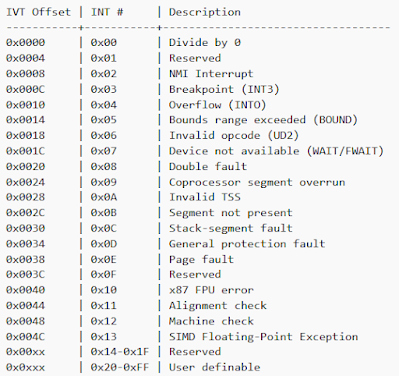
Interrupt Vector Table
We've discussed in this article a wide variety of interrupts. What do all these have in common? They all eventually end up calling routines, called Interrupt Service Routines (ISR), whose addresses are found in the Interrupt Vector Table. After all, there's no sense interrupting the CPU unless you have some job you want it to run. That job is defined in an interrupt service routine which is located by looking up its address in the Interrupt Vector Table. The more modern, Protected Mode name for this is Interrupt Descriptor Table, but the two concepts serve the same ends.
Once the CPU acknowledges an interrupt, be it a software interrupt, hardware interrupt, or the NMI, control is transferred to that interrupt's interrupt service routine. The ISR does its business, and finally calls the IRET instruction to return control of the CPU to the code that was running before the interrupt.
Traditionally, the Interrupt Vector Table is located in 1KB of memory from 0x0 to 0x3FF. In modern times, the table can be relocated. There is room for 256 entries, each representing an address that is 4 bytes in size. The first 32 entries are reserved, and the next 224 can be programmed by BIOS, by I/O peripherals, or a by user.

Conclusion
That concludes our history tour of interrupts. Hopefully you found this useful. As I alluded to in the beginning, each of these sections can probably be its own article, if we were to delve into the details. However, I hope you found value in this review of all the different slices of interrupt history!

Post a Comment
Be sure to select an account profile (e.g. Google, OpenID, etc.) before typing your comment!